How Dartfem Was Made
How I built dartfem, a finite element solver written in Dart.
I am not going to explain how finite element solvers work that is probably going to be a future blog post. Finite element solvers are incredibly complicated and this is already a pretty long blog post.
Why?
Building a finite element solver was part of the Modeling and Programming course (University of Twente). It was not mandatory to do, but I love programming, especially stuff related to engineering and mathematics. The course was given using MATLAB. I don’t really like MATLAB. Also I am really stubborn. I wanted to write it in my favorite programming language, Dart. In my opinion it is a great language that also greatly improved with the release of Dart 3.
Building
Preparation
Before completely committing to building the whole solver in Dart, I first wanted to know if it was even possible. The mainly consisted of figuring out what matrix, vector, and linear solver libraries I was going to use. Because building a finite element solver mainly consists of matrix manipulation, I better make sure that this is actually possible.
Turned out there were no real good libraries for arbitrary matrix manipulation, which was annoying. This meant is was going to have to work with lists of lists. There was, however, a library that did Gaussian elimination. Great. At least I knew that it was possible.
Model definition
The first real step was creating a way for any user to define the model. I chose to do this using a simple object oriented API. This was one of the main reasons I chose Dart instead of MATLAB. Defining the model was now really simple.
1D
At this point I had no idea how hard this challenge was going to be. Making a solver for a single dimension turned out to be a lot harder than I had imagined. Linear algebra was still really new to me at this point. Creating a finite element solver mainly consists of taking the information about the model and transforming that into a single stiffness matrix and a load vector. In one dimension, the size of the stiffness matrix and the vector are equal to the number of nodes. A couple hours into trying to make the solver output correct stiffness matrix, I figured it out. At this point I really did not understand what I was actually doing.
2D
Going from 1D to 2D is a really big step. Suddenly you also need to look at rotations, split up forces, and a lot more. The main practical difference is that in addition to generating a stiffness matrix for each element, you also need to generate a rotation matrix for each element. At this point I began to realize the incredible power of linear algebra. Instead of implementing some insanely complicated piece of logic, you can just think of everything in terms of matrixes and vectors. Understanding that complicated constructs can be represented by a single matrix that can then be multiplied and manipulated is amazing.
Creating the model editor
One of the reasons I chose to use Dart as the programming language for this project was that I could use it with Flutter. I have quite a lot of experience building stuff with Flutter, so quickly setting something up was pretty easy. Turns out when you have complicated relational data it is not trivial to create a editing layer on top of that. There are just so many edge cases that need to be individually handled. For example when you delete a node, there could still be an element referencing that node. I patched this by also deleting the elements that reference that particular node. Great! Problem solved right? Wrong. The solution of the solver still references that node. Things like these can feel like whack-a-mole.
Eventually I got everything stable, granted it took many hours straight of just testing every single scenario. From this point on developing new parts of the solver became a lot easier. I added serialization and deserialization methods to the model definition, which meant the editor could save and load files from disk. I could quickly visualize the displacements, stresses, change the stiffness of the material, and a lot more.
3D
At this point I got bored. I wanted to make the thing work in 3D. The first step was to make the problem definition support 3D coordinates, and updating the editor to have a 3D view. Working with 3D rendering is always a lot of fun, because it is complicated and the output is rewarding; seeing your design come to life in 3D.
Turns out 3D is not part of the course, and there are no resources available for me to learn from. I kept trying to make it work, and after learning even more about rotation matrixes and stiffness matrixes, I eventually got it to work. This, however, took way too much time, and I did it for no real good reason, because of the content that was going to come in the next sessions.
Beams
That next session consisted of adding beam elements. Beam elements can also resist bending, making them more realistic in most cases. They, however, have a much larger stiffness matrix.
Because the resources and teacher assistants assumed the use of MATLAB, I needed to make sure to understand every incredibly well. There was no way anyone was going to help me with anything related to the code.
I began to feel this. Most students just implemented exactly what was written down in the reader. I, however, had committed to 3D, which meant I needed to understand what was done and why it worked.
Looking back at it might seem like a frustrating process. Indeed when I think back on trying to figure out how to construct an element stiffness matrix for a 3D beam I feel the potential for frustration, but I was doing what I love to do, figuring out how stuff works and how I can exploit that. It is the purest form of problem solving; the problem incredibly is well defined.
I did get stuck, however. I ditched the 3D stuff and worked on beam elements, implementing them in 2D. Something interesting I found out is that a model with beam elements will almost never fail solving, but will instead just show really high deformations when the model is unstable. This, for me, was great, since large deformations are still plotted, look at what went wrong, and you can just add another element to make the model stable again.
Preprocessing
In order to allow preprocessing, a large part of the editor program had to be restructured, because it stored the model as a singleton (NEVER use singletons for mutable state). The preprocessing we had to implement was mainly splitting of beam elements, distributed loads, and gravity.
Postprocessing
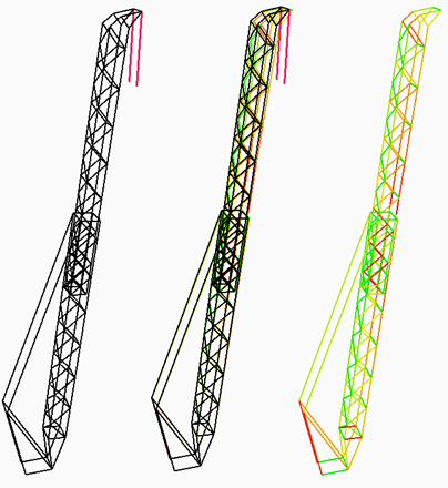
When you have all the nodal displacements, you also need to figure out all the stresses in the different parts of all elements. This is especially complicated for beam elements because every part of the beam has a different stress state. Calculating the max shear stress anywhere in a beam was done by applying Mohr’s circle a couple times and taking the max of a couple critical points. This is then used to generate beautiful images such as the one below.

3D again
I tried 3D again. This time I had a working version to look at. I read every single line of the given MATLAB code many times. I even found multiple bugs in the provided code. This time I had a vastly better understanding of linear algebra and the relation between global and local stiffness matrixes.
During this process I also ran into the single worst bug I have had to solve in my entire life. The solver was working fine in most cases. There were, however, some peculiar edge cases that resulted in obviously wrong solutions. I tested each part of the program extensively, even unit testing some functions against the provided MATLAB implementations. I spent more than 10 hours on this single bug. So what was the problem then? There were two missing - signs in one of the couple large 12x12 matrix definitions. I only discovered it when unit testing the function that returned the matrix against it’s MATLAB counterpart.
I had to make sure that the preprocessing, postprocessing, and everything else also still worked in 3D. A whole category of bugs that I had never had to deal with before was suddenly everywhere. The program compiles correctly, runs without problem, but the output is not quite correct. It’s really difficult to find out what’s wrong, because all the values are numbers and matrixes of numbers, which you cannot inspect to find out what part of the state is incorrect. Often I had to just look at the code and compare that to my understanding of the underlying mathematics.
Looking back
I put about 35 hours into this project. I did end up spending more time in the codebase because I also implemented a model for a project in the solver. I learned so much about the finite element method. Because I did it in Dart, I had to understand everything very well. I love modeling the real world using code. The process is fun and result is extremely powerful. This is probably one of the most difficult but most rewarding and fun projects I have ever done.